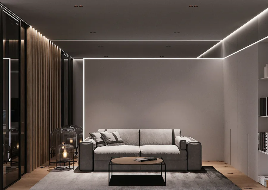
Recessed LED Channel in Drywall: Mud-In Profiles Step by Step
A mud-in profile turns an LED strip into a clean line of light cut into the ceiling. Here's how to plan it, set it, finish it and keep it serviceable.
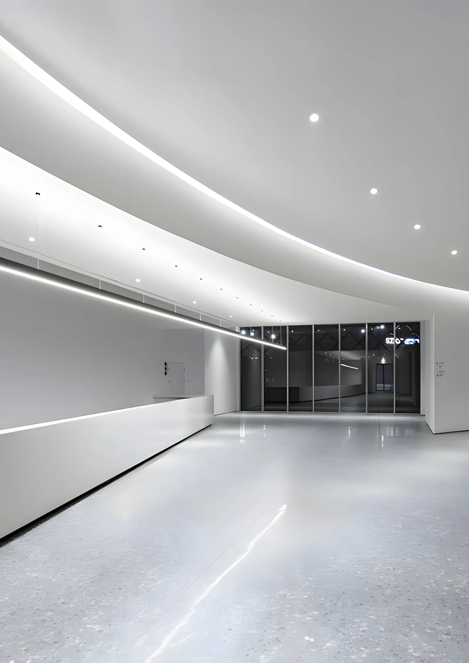
A recessed LED channel in drywall is an aluminum profile set into the board and finished over with joint compound, so all you see is a crisp line of light with no visible trim. These are called mud-in, plaster-in or trimless profiles. The finish depends less on the profile than on the order of work: framing, feeds and access have to be settled before the first sheet of board goes up, and the strip goes in last.
This guide covers the planning, a step-by-step install and the coordination between trades that decides whether the line ends up sharp or cracked.
What a Mud-In Profile Is
A mud-in profile is an aluminum channel with wide, perforated or textured flanges on each side. You fasten it through the flanges to the framing, then tape and mud over the flanges the same way you'd finish a corner bead. Once it's painted, the flanges disappear into the wall or ceiling and only the slot and its lens remain.
Compared with a surface channel, you lose easy access and gain a line that looks built into the architecture. Compared with a cove, you get a direct line of light rather than an indirect glow. If you're weighing the two, our article on cove lighting with LED strips covers the indirect approach.
Where Mud-In Channels Work
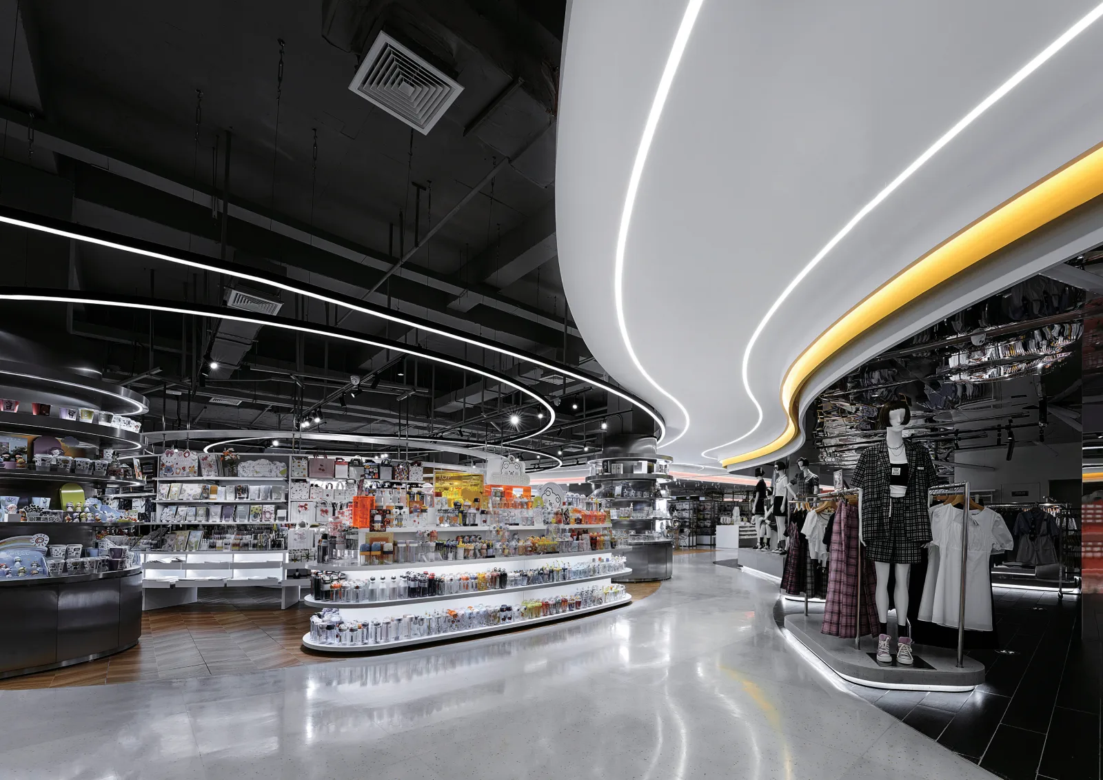
- Ceilings: single lines, grids, perimeter lines a foot or so off the wall, or lines that follow a curve.
- Walls: vertical lines at corners, horizontal lines that read as a reveal.
- Reveals and soffits: a line at the edge of a drop ceiling or bulkhead.
- Stair walls: a line following the stair rake to light the treads.
- Shower and bath walls: only with a strip and lens rated for the location, and with NEC 410.10(D) and the local inspector in mind.
Plan Before the Board Goes Up
Nearly every problem with a recessed channel traces back to a decision that should have been made at framing.
Layout. Snap the lines on the framing, not on the board. Decide where each line starts and stops, how it turns corners, and where the profile lengths will join.
Blocking. Where a line runs parallel to the joists or studs, add continuous blocking so the profile has something solid to fasten to along its full length. Where it runs across the framing, add blocking at every profile joint and every end.
Feed points and lead lengths. Decide where power enters each run. On long lines, feeding from the center or from both ends keeps the brightness even; check the strip's published maximum run in our maximum run length guide. Pull the low-voltage leads (CL2 or CL3 rated cable where it runs in walls and ceilings) to each feed point before board, label them, and leave 12–18 in. of tail.
Driver location. The driver needs a permanent, accessible home: a mechanical room, a closet, an attic with access, or behind an access panel. It must never end up sealed in the ceiling. Size the lead wire for the distance (see the worked example below).
Connections inside the profile. Plan the lead to enter through a hole drilled in the base of the profile near its end. Then the connection to the strip sits inside the channel, where it can be reached later by removing the lens. A splice buried in the ceiling cavity next to the profile can only be reached with a saw.
Profile Size vs Strip and Look
Profile dimensions vary widely between products, so treat this table as general guidance and work from the actual drawings of the profile you choose.
| Profile size (typical) | Strip that suits it | Resulting look |
|---|---|---|
| Narrow slot, about 3/8–1/2 in. wide, shallow | Narrow COB strip | Fine pencil line; COB needed because there's no room to diffuse dots |
| Medium, about 5/8–1 in. wide, 1/2–3/4 in. deep | COB, or high-density SMD | The common ceiling line; even with an opal lens |
| Deep, about 1 in. or more to the lens | SMD or COB | Softest, most uniform line; lens sits well away from the LEDs |
| Wide, about 1 1/2–3 in. | Two strips side by side, or a wide strip | A broad band of light that can serve as ambient light |
| Recessed lens (lens set back in the slot) | Any, chosen by depth | Less glare from below; line reads as a shadow gap that glows |
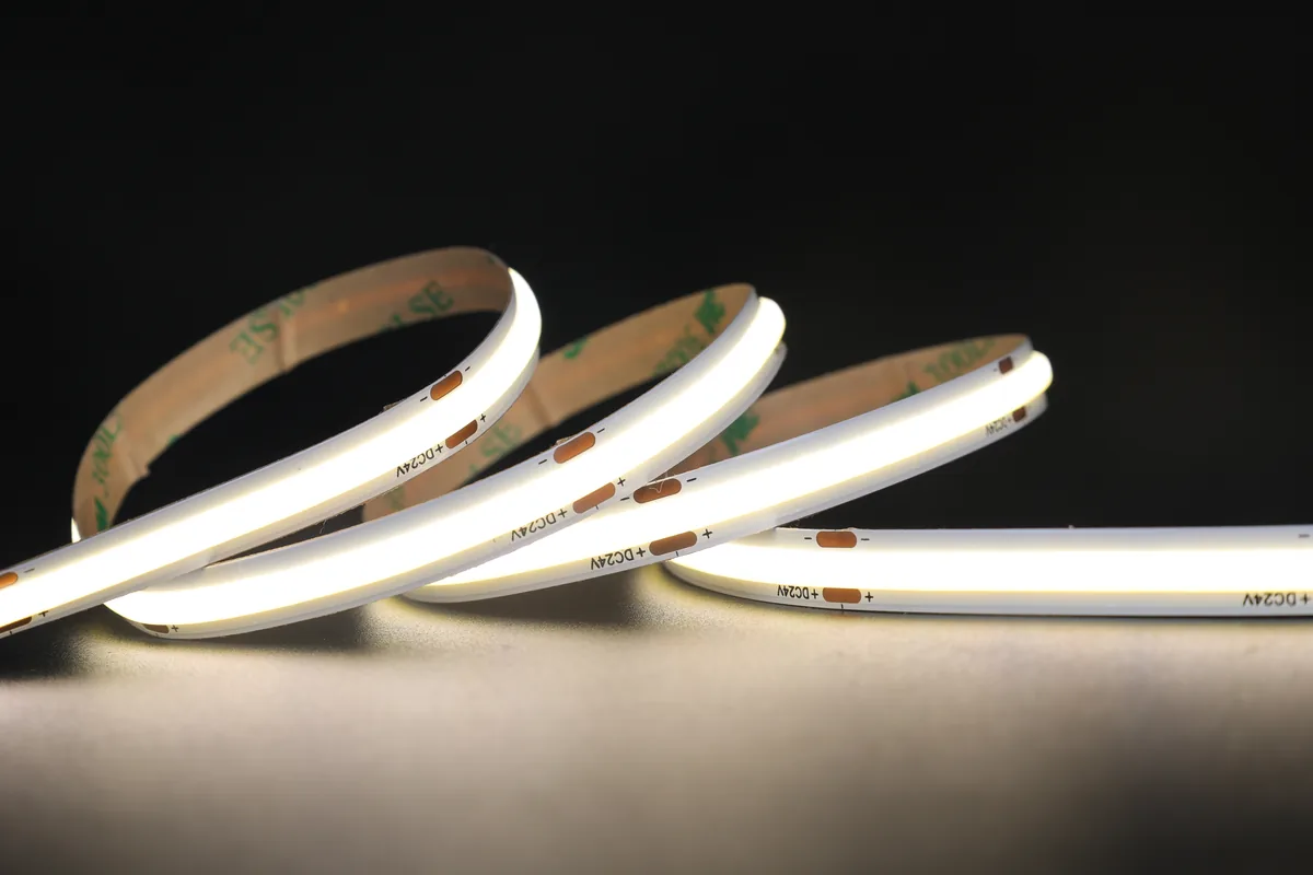
A rough rule for dot-free light: the LEDs disappear when the distance from the strip to the lens is at least the spacing between LEDs. In a shallow profile that's hard to achieve with SMD, which is why COB strips are the default for mud-in work.
Step by Step: Installing a Mud-In Profile
- Dry-fit every length. Lay out the profile on the floor below its line. Cut with a fine-tooth blade for aluminum, deburr the ends, and mark each piece so it goes back in the same order.
- Join lengths and corners. Use the alignment pins or joiners made for the profile. Joints should land on blocking and be offset from drywall butt joints. Use factory corners where they exist, or miter carefully and back the joint with blocking.
- Drill the feed holes in the profile base at each planned feed point and pull the labeled leads through.
- Hang the board. Depending on the profile, the board either butts to a profile already fixed to the framing, or a slot is cut in the board and the profile's flanges sit on its face like a corner bead. Follow the profile's instructions. Keep the cut edges tight to the profile body; big gaps mean thick mud, and thick mud cracks.
- Fasten through the flanges into the framing or blocking with drywall screws, typically every 8–12 in. (follow the profile's fastening spacing). Check the line with a straightedge or laser as you go. The flange must sit flat with no rocking.
- Protect the slot. Many profiles ship with a protective strip or cap. If yours doesn't, mask the opening with tape. Mud in the slot is the hardest mistake to undo.
- First coat: tape and setting compound. Bed mesh tape over the joint between flange and board and cover it with a setting-type (chemically curing) compound. It shrinks less than premixed compound and bonds better to the flange.
- Second and third coats. Feather each coat wider, typically 8–12 in. on each side of the profile, so the slight build of the flange disappears. Let each coat dry fully.
- Sand and check with a raking light. Hold a work light flat to the surface. A flange you can see in raking light will show forever once the line is lit.
- Prime and paint. Remove the protective strip, clean the slot edges, then prime and paint. Keep paint out of the clip grooves where the lens seats.
- Install the strip and lens last. Wipe the inside of the channel clean and dry, test the strip on the bench, stick it to the base, connect the leads, test again in place, then snap in the lens and fit the end caps.
Diffusers and Strips
For a mud-in line the lens is the finish, so choose it on purpose.
- Opal (frosted) lens: hides the individual LEDs and gives a uniform line. The right default for almost every ceiling slot.
- Clear lens: highest output, but every LED shows. Rarely right in a visible slot.
- Flush vs recessed lens: a flush lens reads as a glowing stripe at the surface. A recessed lens sits back in the slot and cuts glare when you look up at it.
For the strip, COB gives the smoothest result in shallow channels. Match the CCT to the room's other lighting and specify a tight color consistency if lines will be seen side by side. The profiles and diffusers guide goes deeper into lens types and output loss.
Heat, Access and Replacing the Strip Later
A mud-in profile is buried in gypsum, often with insulation above it. Drywall is a poor heat conductor, so the aluminum has less help than a surface channel in open air. Keep strip wattage moderate in shallow buried profiles, check the profile's spec sheet for a maximum W/ft if it gives one, and never let spray foam or insulation pack tight against the back of the channel.
Replacing the strip is straightforward if the plan above was followed: pop out the lens, disconnect the lead inside the channel, peel the strip (warming the adhesive gently helps), clean the base and stick in a new strip of the same width. If the connections were buried outside the channel, the same job means cutting the ceiling.
Worked Example: A 24 ft Ceiling Line
A 24 ft mud-in line with a 24V COB strip at 4 W/ft. Use your strip's actual wattage from its spec sheet.
- Total load: 24 ft × 4 W/ft = 96 W. On one driver that's 96 ÷ 0.8 = 120 W, above the 100 VA limit of a Class 2 power source.
- Split it: feed the line as two 12 ft halves, each on its own driver. Each half is 12 × 4 = 48 W, so 48 ÷ 0.8 = 60 W per driver. Current per half is 48 ÷ 24 = 2 A.
- Lead wire: the drivers sit in a closet 25 ft away. With 18 AWG: drop = 2 × 25 × 2 × 0.006385 Ω/ft = 0.64 V, about 2.7% of 24V. Acceptable.
- If the closet were 40 ft away: 18 AWG gives 2 × 40 × 2 × 0.006385 = 1.02 V, about 4.3%. Moving up to 16 AWG brings it to 0.64 V, about 2.7%.
Each 12 ft half is also well inside the maximum run of most 24V strips, though that figure depends on the product. The power supply calculator handles the sizing for other lengths.
Who Does What: Trade Sequence
Mud-in profiles fall between trades, and that's where most jobs go wrong. Put the scope in writing.
- Framer: blocking at every line, joint and end.
- Electrician or lighting installer (rough-in): feed leads to each point, driver location prepared with power, before insulation and board.
- Profile installation: either the lighting installer or the drywall hanger sets and fastens the profile. Agree on which, and on who supplies it.
- Drywall finisher: tapes and muds the flanges with the slot protected. Brief the finisher on setting compound for the first coat and on keeping the slot clean.
- Painter: primes and paints with the protective strip removed and the clip grooves kept clean.
- Electrician or lighting installer (trim-out): strip, lens, end caps, drivers, testing.
Common Mistakes
- Cracks along the flanges. Usually no tape over the flange, premixed compound in the first coat, or a profile fastened to board with no blocking behind it.
- Mud in the slot. It hardens in the clip grooves and the lens won't seat. Protect the slot until paint.
- No access to connections. Splices buried above the ceiling, or a driver sealed in a soffit. Bring leads into the profile and keep the driver somewhere you can reach.
- Wrong lens. A clear lens over SMD in a shallow slot gives a row of dots on a ceiling that cost a lot to finish. Use opal and COB.
- Mismatched lengths. Strip cut lengths that don't fit the profile leave dark gaps at the ends, and short pieces of diffuser leave a dark line at every joint. Plan strip cut points and diffuser lengths against the profile layout before you order.
Frequently asked questions
What is a mud-in LED channel?
A mud-in (plaster-in) channel is an aluminum LED profile with perforated flanges that are taped and covered with joint compound, so only the lens shows once the wall or ceiling is painted.
When do you install a recessed LED channel in drywall?
The profile goes in after the board is hung (or with it) and before taping and mudding. The LED strip and diffuser go in last, after painting.
How do you keep a mud-in LED profile from cracking?
Fasten the profile to solid blocking, bed mesh tape over the flanges in setting-type compound, and feather the following coats wide. Cracks usually come from no blocking, no tape or a thick first coat of premixed compound.
Can you replace an LED strip in a plaster-in profile?
Yes, if the connections were planned inside the profile. Remove the lens, disconnect the lead, peel out the old strip and fit a new one of the same width.
What LED strip is best for a recessed drywall channel?
COB strip with an opal lens gives a smooth, dot-free line in shallow channels. Deeper profiles also work well with high-density SMD.
Specify with ENKORA
Working on a project? Send us the drawings and we will propose strips, profiles and drivers that fit together.