Addressable LED Strip Types for Architectural Projects: SPI vs DMX
SPI or DMX? How each pixel control system works, how to count pixels and universes, and how to power and plan an architectural pixel install.
Addressable LED strip types come down to two control families: SPI, where a pixel controller sends a data stream straight down the strip, and DMX/Art-Net, where a lighting console or media server talks to decoders mounted near the strip. Both let you set the color of every pixel on its own. SPI is simpler and cheaper for a single feature. DMX and Art-Net scale to facades, long lobby coves and synchronized shows. Which one fits depends on run distances, pixel count and who will program the lighting.
Below: how each system works, how to count pixels and universes, how to power long runs, and how to plan an architectural install so it doesn't turn into a rewire.
What "Addressable" Actually Means
On a standard RGB strip, every LED shows the same color at the same time. The controller changes three channels (red, green, blue) and the whole run follows.
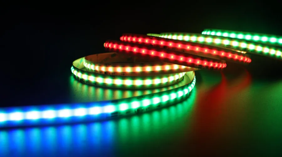
An addressable strip adds small driver ICs along the board. Each IC receives data, keeps the part meant for it, and passes the rest along. The LEDs that one IC controls form a pixel. On some strips a pixel is a single LED package. On many 12V and 24V strips, one IC drives a short group of LEDs, so the pixel is that group, and the cut interval usually matches it.
Pixel size matters for design. A chase on a strip with long pixel groups looks blocky up close; on a facade seen from across the street it can look perfectly smooth. Check pixels per foot on the spec sheet before you promise an effect. If you're new to pixel strip, RGB vs addressable in the Lighting Guide covers the basics.
How SPI Pixel Control Works
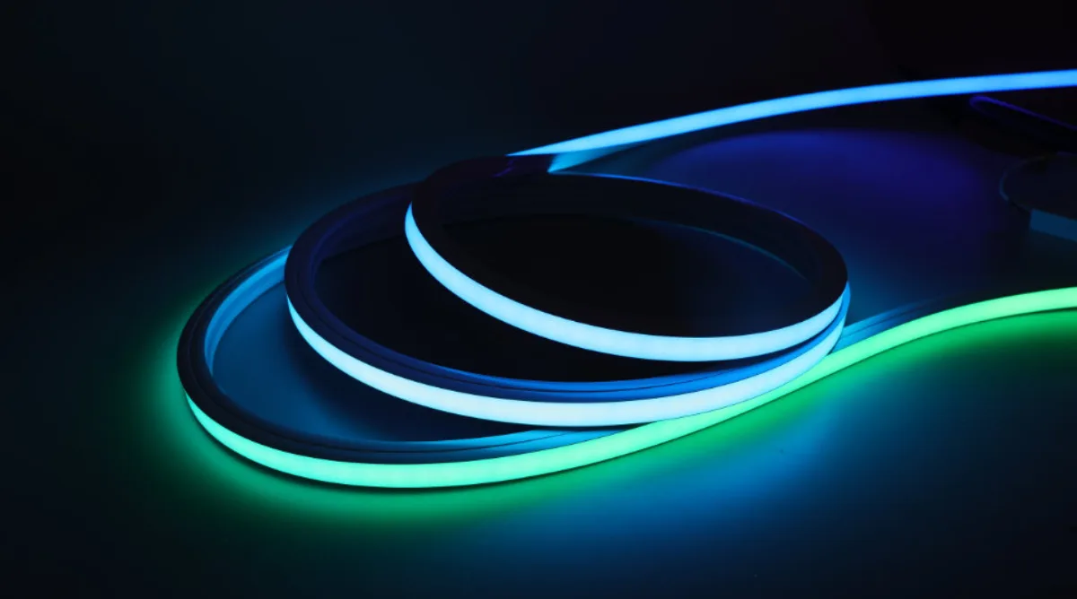
SPI is the most common way to drive addressable strip. A pixel controller generates a serial data stream and sends it into the first pixel. Each IC reads its own data and shifts the rest down the line, pixel by pixel. A few practical rules follow from that.
- Data runs one way. The strip is marked DI (data in) and DO (data out), with arrows printed along the board. The controller connects to DI. Feed the DO end and the strip stays dark even with full power on it.
- The first data hop is the weak link. The signal leaving a basic controller is a low-voltage logic signal, not built for long cable. Keep the run from controller to first pixel short. Typical limits run from a few feet to a few tens of feet, depending on the controller and the protocol. If the controller has to live farther away, use a signal amplifier or a controller with long-line (differential) outputs, and check its spec sheet for the supported distance.
- Each pixel rebuilds the signal. Once data reaches the strip, every IC regenerates it on the way out, so the distance from pixel to pixel isn't a problem. Trouble comes from the cable before the first pixel and from long jumpers between segments.
- Single-wire vs data plus clock. Common IC families use one of two schemes. Single-wire protocols send data on one line and depend on precise timing. Two-wire protocols add a clock line, which makes them more tolerant of timing variation. The controller has to support the protocol your strip uses, so read the IC type off the spec sheet and set the controller to match.
Backup data lines
On a strip with a single data line, one dead IC breaks the chain: every pixel after it goes dark or shows garbage. Some strips add a backup data line, so each IC can also receive data from the pixel two places back. If one pixel fails, the next one still gets its signal, and the run keeps working with a single dark pixel. In architectural work, where a failed pixel may sit behind a finished soffit, that's worth asking for. Check the spec sheets of the strips in the addressable collection for it.
SPI controllers range from small units with one or two outputs to multi-output controllers that play stored shows on a schedule. Every output has a maximum pixel count, so a larger job may need several outputs or several controllers. When you pick one from controllers, confirm three things: the IC protocol, the pixels per output, and the number of outputs.
How DMX and Art-Net Pixel Control Work
DMX512 is the control standard of entertainment and architectural lighting. One DMX line carries a universe of 512 channels, each with a value from 0 to 255. A console, a lighting control system or a media server sets those values, and each device listens for the channels it's been addressed to.
Pixel strip doesn't read DMX directly. A DMX-to-SPI decoder sits near the strip, listens to a block of DMX channels, and turns them into the SPI data stream the strip understands. The long run is DMX cable; only the last short hop is SPI. That's why DMX scales well: it travels on shielded twisted-pair cable using RS-485 signaling, is commonly planned for runs of up to about 1,000 ft (300 m) per line with a terminator at the far end, and supports up to 32 devices on a line segment before you need a splitter.
The channel math is fixed:
- An RGB pixel uses 3 channels. 512 ÷ 3 = 170 pixels, which uses 510 channels and leaves 2 spare.
- An RGBW pixel uses 4 channels. 512 ÷ 4 = exactly 128 pixels.
Designers rarely split one pixel across two universes, so plan on 170 RGB or 128 RGBW pixels per universe and start a new universe after that.
Large projects need dozens of universes, and that's where Art-Net (or the similar sACN protocol) comes in. Both carry many DMX universes over standard Ethernet. The console or media server sends data through a network switch to Art-Net pixel controllers, or to Art-Net nodes that feed DMX decoders, mounted near the strips. Ethernet follows normal network rules: 328 ft (100 m) per Cat5e or Cat6 segment between switches, with fiber for longer backbones.
On these systems the content usually comes from pixel-mapping software. The designer lays every pixel out on a drawing of the building, then plays video or generated effects across that map. That's how a smooth wave can cross a facade built from dozens of separate strips.
SPI vs DMX/Art-Net Side by Side
| SPI (pixel controller) | DMX / Art-Net (console or server + decoders) | |
|---|---|---|
| Control distance | Short data run to the first pixel; amplifiers extend it | DMX: long RS-485 lines; Art-Net: 328 ft per Ethernet segment, fiber beyond |
| Practical scale | One feature up to a few thousand pixels, set by controller outputs | Thousands to tens of thousands of pixels, set by universes and network design |
| Programming | Built-in effects, an app, or stored shows on the controller | Console, lighting control system or media server with pixel mapping |
| Integration | Usually standalone | Ties into building lighting control, show control and timeclocks |
| Cost | Lowest: one controller, little cabling | Higher: decoders, console or server, network gear and programming time |
| Typical projects | Bar fronts, signage, stair features, retail displays, residential accents | Facades, bridges, lobbies, venues, hotels, multi-zone shows |
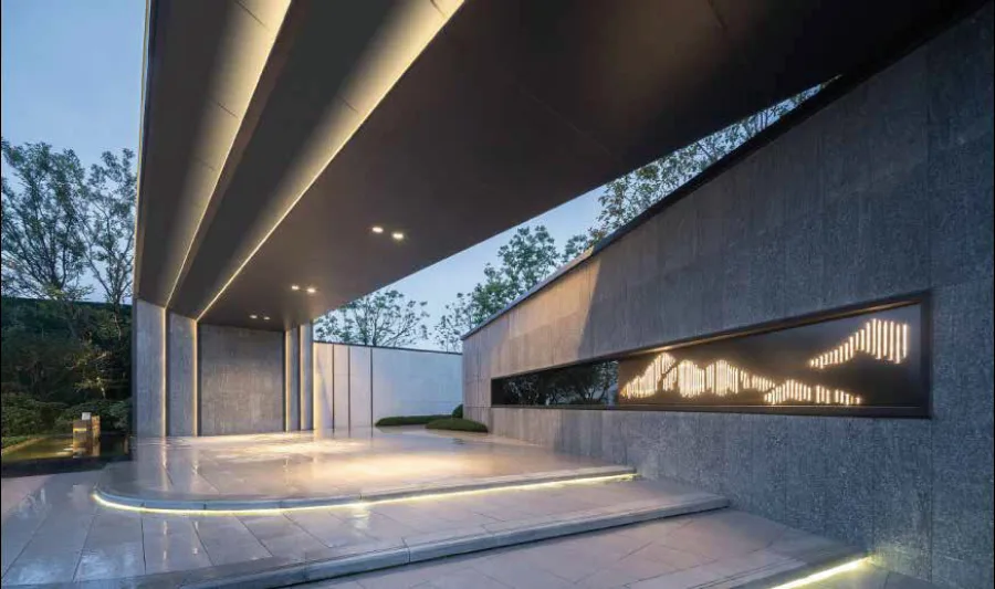
Neither is better in general. A backlit bar front with a slow color drift is a perfect SPI job. A hotel facade that runs a holiday program, syncs with the lobby and gets reprogrammed by the venue's lighting operator is a DMX or Art-Net job from day one.
Powering Long Pixel Runs
Pixel strip draws the most current at full white, with every channel on. The usual voltage drop rules apply, but the symptom is different. As voltage falls toward the far end of an RGB run, the blue and green LEDs, which need a higher forward voltage, lose output first. Full white at the near end turns warm, yellowish or pinkish at the far end, and that color shift shows before any obvious dimming.
The fix is power injection: feeding power into the strip at more than one point.
- Feed both ends of a run, or inject at intervals within the maximum single-feed run length on the strip's spec sheet.
- Size the feed wire for the current and distance. The wire gauge chart has the voltage drop numbers for 12V and 24V.
- When separate power supplies feed different sections, don't tie their positive outputs together. Cut the V+ between sections on different supplies, and keep the data line and the ground continuous.
- Every controller, decoder and power supply on a pixel run needs a common ground. The data signal is read against ground; without a shared reference, pixels flicker, show random colors or don't respond.
- Size each power supply at full-white load ÷ 0.8. The power supply calculator does that math.
Planning an Architectural Pixel Install
- Map the pixels. Draw every run on the plans with its length, then convert to pixels using the strip's pixels per foot. Number the runs in the order data will flow.
- Pick the color format. RGBW uses a third more channels than RGB. Decide before you count universes.
- Count universes. Divide pixels per run by 170 (RGB) or 128 (RGBW). Break runs at universe boundaries where you can, so one run doesn't straddle two universes in an awkward spot.
- Locate controllers and decoders. Put them close to where each run starts, in accessible, ventilated spots. Keep every SPI data hop short.
- Plan the power feeds. Mark injection points, power supply locations and the wire gauge for each feed. Power supplies need to stay reachable for service.
- Route the data cable. DMX on shielded twisted pair, daisy-chained with a terminator on the last device; Art-Net on Cat5e or Cat6 back to a switch. Keep low-voltage control wiring separated from line-voltage conductors as code and the manufacturer require.
- Document the addresses. Label every decoder with its universe and start address, and give the programmer a pixel map that matches what was built.
Low-voltage lighting systems fall under NEC Article 411, and Class 2 circuits under Article 725. Confirm the requirements for your project with the local inspector or a licensed electrician.
Worked Example: 60 ft of Pixel Strip in a Lobby Cove
A lobby cove takes 60 ft of 24V RGB pixel strip. For this example, assume 18 pixels per foot. That's an example figure, not an ENKORA spec; pixel density varies by product, so use the number on your strip's spec sheet.
- Pixels: 60 ft × 18 px/ft = 1,080 pixels.
- Channels: 1,080 × 3 = 3,240 DMX channels.
- Universes: 1,080 ÷ 170 = 6.35, so 7 universes. One universe holds 170 pixels, so break the cove into 9 ft segments (9 × 18 = 162 pixels each). Six of them cover 54 ft, and a 6 ft segment (108 pixels) finishes the run: seven segments, seven universes.
- If the cove were RGBW: 1,080 ÷ 128 = 8.44, so 9 universes. A universe now holds 128 ÷ 18 = 7.1 ft of strip, so use 7 ft segments (126 pixels): eight of them plus one 4 ft segment.
- Power: assume, again as an example, 4 W/ft at full white. 60 ft × 4 W/ft = 240 W, or 10 A at 24V. Split the cove into three 20 ft sections of 80 W each (3.33 A). With the 80% rule, each section needs 80 ÷ 0.8 = 100 W of supply capacity.
- Feed wire: with the supply 30 ft from its section, 14 AWG drops 2 × 30 ft × 3.33 A × 0.002525 Ω/ft = 0.51 V, about 2.1% of 24V. 16 AWG drops 0.80 V, about 3.3%. Both work; 14 AWG leaves more margin at full white.
Seven universes is more than one DMX line carries, since each line is a single universe. A job like this would normally run Art-Net or sACN to a multi-output pixel controller mounted near the cove, or to a set of decoders fed from Art-Net nodes.
Common Mistakes
- Data fed into the wrong end. After cutting, it's easy to flip a piece. Follow the arrows from DI to DO. If a cut section stays dark, work through LED strip not working after cutting.
- Long unbuffered data runs. A pixel controller in a mechanical room 60 ft away with plain wire to the first pixel gives flicker, random colors or nothing at all. Move the controller or decoder next to the strip, or use an amplifier or long-line outputs.
- No common ground. A controller on one supply and the strip on another, with grounds not tied together, is the classic cause of random colors.
- Underestimating the universe count. It's 512 channels per universe, not 512 pixels. RGBW uses four channels per pixel, and pixels don't split across universes. Budget decoders and controller ports on the real number.
- One feed on a long run. The far end turns pink or yellow at full white. Inject power.
- Decoders and supplies buried in finished walls. Every active component will need service at some point. Keep them accessible.
- No time budgeted for programming. A DMX or Art-Net system does nothing interesting until someone builds the content. Agree on who programs it before the bid.
Frequently asked questions
How many pixels can one DMX universe control?
A DMX universe has 512 channels. An RGB pixel uses 3 channels, so one universe controls 170 RGB pixels. An RGBW pixel uses 4 channels, so one universe controls 128 RGBW pixels.
What is the difference between SPI and DMX LED strip control?
With SPI, a pixel controller sends data directly into the strip over a short cable. With DMX or Art-Net, a console or media server sends data over long cable runs or a network to decoders placed near the strip, which convert it to the strip's SPI data.
How far can the data wire run from an SPI controller to the strip?
Not far. Typical limits run from a few feet to a few tens of feet depending on the controller and protocol. For longer distances, use a signal amplifier, a controller with long-line outputs, or a DMX/Art-Net decoder mounted next to the strip.
Do addressable LED strips need power injection?
On long runs, yes. Without it, the far end shifts toward yellow or pink at full white because blue and green lose output first as voltage drops. Feed power at both ends or at intervals within the strip's published maximum run length, with a common ground throughout.
Can a lighting console control addressable LED strip?
Yes, through DMX-to-SPI decoders or Art-Net pixel controllers. The console or media server treats each pixel as a set of DMX channels, and the decoder converts those channels into data the strip understands.
Specify with ENKORA
Working on a project? Send us the drawings and we will propose strips, profiles and drivers that fit together.